
Royal University of Phnom Penh
Faculty of Engineering
Dep. of Telecommunication and Electronic Engineering
Course: Electronic System Design
Project Title:
Smart Detecting Train Auto Control Gate
Group member:
Ly Seyha, Tann Thona, Chhoy Noreath, Nop Da, Ham Sovann Simpich Dany
Advisor: Chan Tola
1st Generation, Year 4th Semester I
2017-2018
 |
| Project Smart Detecting Train Auto Control Gate |
Smart Detecting Train Auto Control Gate
I. Abstract
In this article, we aim to build an electronic project is a Smart Detecting Train Auto Control Gate to control traffic of the quadrilateral road of the train and cars road. In this project, we will use 3 main controllers; microcontroller, sensor, and servo motor. we have developed it by invented a new board as Arduino board by using an ATmega328P microcontroller instead of Uno Arduino to control the project process, IR sensor type of TCRT5000 to cooperate with our new board to detect the train coming and then feedback the signal to the microcontroller for control the traffic light, buzzer and servo motor for on/off gate to prevent accident of cars and the train. The invention of the new board is too many steps to do, we will show the board invention of each step in the detail of article below. We have made a new board in order to control the process instead of the Arduino board, so this is a powerful project that we can make a PCB by our own.
II. Introduction
In Cambodia, nowadays there is not so strong in using electronic system to control the system along the railroad, usually we see just the manual system in this case, so we will have an idea to make a system which it works automatically by electronic components in it. This is called Smart Detecting Train Auto Control Gate, it is an Arduino project which we built it with the process commonly as the reality in training process. It is working by automatically in detecting the coming train in a specific distance and then command to traffic light and on-off the gate. It is a powerful project that we have developed by using a main board of a new making PCB with a ATmega328 instead of using the Arduino board in controlling the whole process of our project. In this project, we have used two more important components: servo motors and sensors. we used IR sensor type TCRT5000 to detect train and feedback to a microcontroller while the train is coming for control the traffic light, buzzer and on/off gate to stop cars by servo motors for prevention accident at the quadrilateral road between cars road and railroad. There are 6 pairs of IR sensor along the two part of railroad which there are 3 pairs of sensors to control a direction and 3 more pairs to control another, we have arranged it because we have imagined that we need more safety and smoothly to process on it. Two servo motors are used in controlling in on/off gate when the train coming and across and the traffic light is just used LEDs to output.
We made it up in order to:
- To learn about electronic components.
- To show the powerful of electronic components in automatically working.
- To understand the process in developing project and in reality
- To compare process in project and reality working.
- To know the designing of PCB by using software.
- To know about making a new PCB as Arduino.
- To show that we can making a controller PBC by our own selves.
III. Electronic Requirement
Base on this whole project, some requirement electronic components is list below:
- Mini Servo x2
- ATmega328P x1
- Crystal 16MHz x1 and Capacitor Ceramic 22pF x2
- IR sensor (TCRT5000) x6
- LDR Sensor x1
- LED (Red x3, Greenx2, Yellow x2 and White x8)
- Resistor (10Kohm x7, 330ohm x 6 and 100ohm x2)
- Capacitor Ceramic (100nF x2)
- Capacitor Electrolyte 10uF x2
- Adapter DC 9 or 12V (1 - 1.2A)
- 12vDC Connector x1
- Switch 12v x1
- Terminal Block 2pins x1
- Button x1
- Regulator (L7805) x1
- PCB (77mm x 72mm)
- Jumper wire
1. TCRT5000 IR Sensor
There are two IR LEDs in a TCRT500 that blue LED is transmitter and black LED is a receiver. IR receiver is a potentiometer that is resistor has value depend on IR light.
It works by transmitter LEDs transmit the IR light while the receiver receives the IR light by reflecting signal from object to making change the resistance value. The resistance value of transmitter should be the same of LED’s resistance value and receiver should more than 1Kohm. See Figure 1 below for IR Sensor characteristic and Its working.
 |
| Figure 1: IR Sensor characteristic and Its working. |
2. Servo Motor
In this project, we use servo motor to control to on-off gate when the train goes through that way.
- It operates voltage from 4.8 – 6v
- Stall torque: 1.8 kg.cm (4.8V), 2.2 kg.cm (6 V)
- Operating speed: 0.1 s/60 degree (4.8 V), 0.08 s/60 degree (6 V).
 |
| Figure 2: Servo motor specification. |
3. ATmega328P
We used ATmega328P instead of Arduino board process of controlling, it is operating well with 1.8-5.5V of input voltage. It needed a crystal clock with two ceramic capacitors and a 10KOmh resistor and a button for reset to working our microcontroller.
- Pin 1 is a reset pin to connect with a button.
- Pins 2&3 are the Rx and Tx pins.
- Pins 4 to 6 and 11 to 19 are the output digital pins.
- For pins 7&8 are the power pins of VCC and GND.
- For pins 9&10 are the connection pins of crystal with 2 capacitors.
- For pins 23-28 are the output analog pins.
 |
| Figure 3: Pins connection diagram for ATmega328P. |
IV. Methodology
1. Making Print Circuit Board(PCB)
1.1 PCB Software Design
Base on this project, we have used 2 kind of software programs of Proteus to make new a PCB:
 |
| Figure 4: Interface of Proteus ISIS design circuit schematic with v7.10. |
 |
| Figure 5: Interface of Proteus ARES design layout diagram with v7.10. |
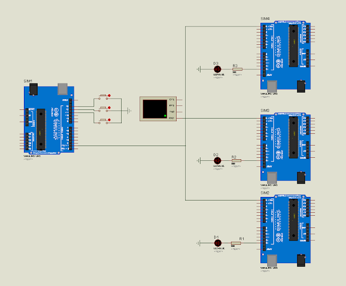
- Proteus ISIS software v7.10: is used to draw the circuit diagram by connecting from any components which we necessary need for our project. It is also corporates to an ARES software program. See Figure 4 below for ISIS design.
- Proteus ARES software v7.10: used to draw a layout of PCB diagram which connect form ISIS schematic design. See Figure 5 below for ARES design layout diagram.
*Note: in these combining program, some package may not have in this software, so you need to draw it by manually.
Go to this link to download software of the Proteus.v7.10 for the designing circuit schematic and diagram: Download Proteus.v7.10 Software
1.2 PCB Hardware
After we already design the diagram in Proteus software, then we need to follow these below steps:
 |
| Figure 6: Making PCB hardware with step by step. |
These above figures show the steps of how to make a new PCB:
- For Fig6.1, show the printing out of the circuit drawing on a slipper paper by the Laserjet printer.
- Fig6.2, Iron that printed paper on the PCB board with a specific size.
- Fig6.3, Put the PCB which already ironed into acid and making vibrate it carefully.
- After we finish these 3 steps above then we need to apply all components to PCB board of each its position and then soldering it one by one. See Fig6.4&6.5.
V. Experiment
1. Program on ATMEGA328P Microcontroller
This is the explains how to migrate from an Arduino board to a standalone the ATmega328P microcontroller on a breadboard for burning the bootloader and uploading program to it.
Unless you choose to use the minimal configuration described at the end of this tutorial, we'll need four main components (besides the Arduino, ATmega328, and breadboard):
- a 16 MHz crystal,
- a 10k resistor, and
- two 18 or 22 picofarad (ceramic) capacitors.
1.1 Burning the Bootloader
We need to burn the bootloader onto a new ATmega328P microcontroller by using an Arduino board as an in-system program (ISP).
 |
| Figure 7: Wire connection to burn the bootloader onto an ATmega328P with Uno Arduino. |
We’re choosing an Uno Arduino board for this section, so to burn the bootloader, we need to follow these below steps:
- Firstly, need to upload the ArduinoISP sketch onto an original Arduino board by select the board and serial port from the Tools menu that correspond to our board.
- Wire up the Arduino board and microcontroller as shown in the diagram of Figure7.
- Select "Arduino Duemilanove" from the Tools -> Board menu and then select to ATmega328.
- Select "Arduino as ISP" from Tools -> Programmer
- Run Tools -> Burn Bootloader
You should only need to burn the bootloader once. After you've done so, you can remove the jumper wires connected to pins 10, 11, 12, and 13 of the Arduino board.
1.2 Uploading Using an Arduino Board
After ATmega328P has the Arduino bootloader on it, then we can upload programs to it by using the USB-to-serial convertor (FTDI chip) on an Arduino board.- To upload our code onto it, need to remove the microcontroller from the Uno Arduino board so the FTDI chip can talk to the microcontroller on the breadboard instead.
- Connect the RX and TX lines from the Arduino board to our ATmega328 on the breadboard as shown in Figure 8.
- To program the microcontroller, select "Arduino Duemilanove " from the the Tools > Board menu and select ATmega328, then upload as usual.
 |
| Figure 8: Wire connection to uploading sketches code to an ATmega328P on a breadboard. |
1.3 Algorithm of Project
In this section, we will introduce you to know about our project processing in the diagram, see Figure 9 below to understand well.
To make a process in this project, we need to do the coding. For coding, you can download in link:
 |
| Figure 9: Processing of Smart Detecting Train Auto Control Gate. |
 |
| Figure 10: Flow Char |
VI. Result
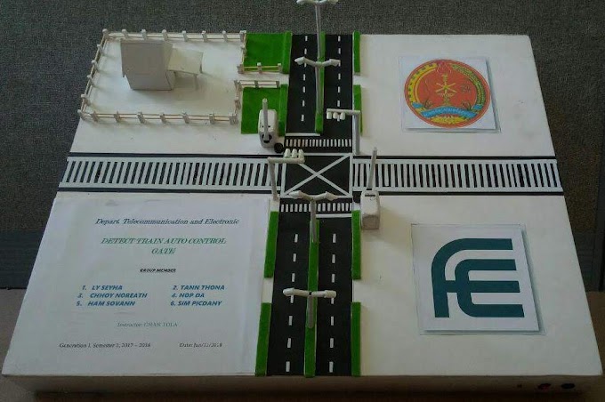
After we spent 10 weeks to develop it, finally we have completed it with 90% of fully project.
According to this project, there are two main parts, the smart detecting train system and auto night light system on this project. Let see the result of our full project’s demo is in the link below.
According to this project, there are two main parts, the smart detecting train system and auto night light system on this project. Let see the result of our full project’s demo is in the link below.
 |
| Figure 11: Result of Smart Detecting Train Auto Control Gate. |
VI. Conclusion
In sum, we have developed an electronic project which work automatically to traffic light and gate control by detecting the coming train at quadrilateral road. We have made a new PCB board which include a new chip ATmega328P and all-important components on it to cover to a whole project’s process that can be replacement to an Uno Arduino board. Finally, it is working 90% of fully project and we need to update it with any remaining part and something lost in order to finish our project completely.
After we have finished this project, we knew many things about this project:
- Knew some electronic components characteristic and its specification.
- Understood the process in developing project and in reality.
- Know the comparing of process in project and reality working.
- Understood well about the designing of PCB by using Proteus software.
- Knew about how making a new PCB and boot-loading the ATmega328P as Arduino.
Reference
[1]. https://www.arduino.cc/en/Tutorial/ArduinoToBreadboard
[2]. https://nomada-e.com/store/sensores/9-sensor-optico-reflectivo-tcrt5000.html
[3]. http://full-parts.com/mg90s-metal-gear-servo-for-arduino-micro-tower-pro-180-degrees.html
[4]. https://voidyourwarranty.wordpress.com/2014/08/17/using-arduino-as-an-isp-to-program-a-standalone-atmega-328p-including-fuses/


1 Comments
I really liked your Information. Keep up the good work. Sim so dep
ReplyDelete