

Measure Output Current on SIMetrix
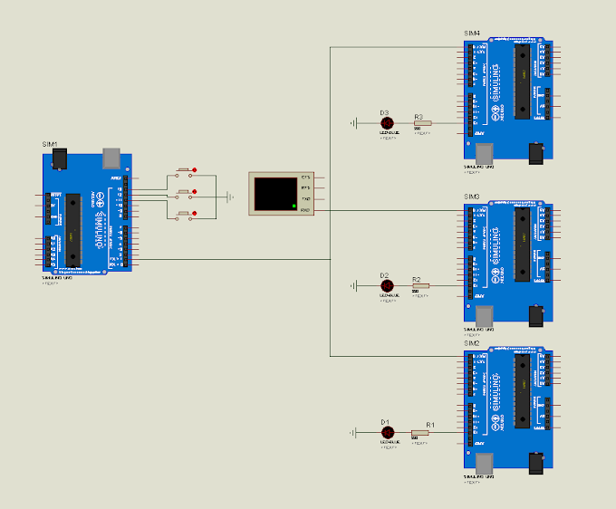
LDO model packet and test circuit for output voltage
 |
| Fig 1. LDO model packet and test circuit for output current |
Objective
We want to know how much current our LDO can supply until OCP (Over Current Protection) circuit work and disable VOUT.
Condition
- VIN = 5V because test circuit has high dropout.
- VOUT(S) = 1.5V
Procedure
To simulate output current we will need to sweep resistor R1 from maximum to minimum value so that IOUT will increase from minimum to maximum due to Ohm’s Law I = V / R
- R --> ∞ then I --> 0
- R --> 0 then I --> ∞
But we can’t sweep R1 in SIMetrix, so we are going to do it in another way. We connect VOUT_Pto a voltage source V2 in this case, VOUT_P = V2– IOUT x R1. The value of R1 is set to be very small (R1 = 1µΩ) so that VOUT_P is equal to V2(and to be able to probe the output current).
We know that VOUT will drop to zero when IOUT reach its maximum value, so we will sweep V2, which is equal to VOUT, from 1.5V (VOUT(S) = 1.5V) to zero and probe VOUT and IOUT we will get the curves of the two.
 |
| Fig 2. Choose analysis voltage |
Result
Run SIMetrix circuit simulator

Then, we select the two curves and compare them on the graph to see how VOUT acts when we sweep IOUT.

As we can see, IOUT is now the X axis which sweeps from 0 to 140mA and the red curve is VOUT . The output current the current at which the output voltage becomes 95% of VOUT(E) after gradually increasing the output current. VOUT(E) = 1.497V, so 95% of VOUT(E) is 1.41972598V. As we can on the graph, IOUT = 136mA at 95% of VOUT(E). After 136mA, VOUT is drawn to zero and IOUT is drawn back to 15mA by OCP.
Hence, output current is IOUT = 136mA.
Hence, output current is IOUT = 136mA.


0 Comments